
Raising the Bar for Artemis Program’s PPE Solar Array Simulation Frame — Part II
In our previous blog post we discussed the mechanical challenges in designing the solar simulator motion system to test NASA’s Power and Propulsion Element (PPE) solar arrays. We designed, engineered and fabricated a custom mobile-robot gantry to reduce system cost and complexity. In addition to addressing stability and lifting challenges as discussed previously, we also addressed construction, mobility and electrical challenges.
Piece by Piece
The vertical tower supporting the solar simulator load will reach three stories high when fully constructed. Because it was too tall to fit inside the building where it was made, the tower was built in three pieces. We made a shorter counterbalance cable set to allow the bottom section to be used for full functional testing within the low ceiling of our assembly bay.
As the lift travels up the completed vertical tower, any vibrations induced by imperfections where each section is connected would impact the simulator performance and diagnostic quality. We joined each tower section with a special multigenerational method of splicing, similar to our long-travel gantry systems. These universal splicing joints enable smooth vertical motion across the splices.
Getting Around
The motion system’s actuation is manually operated except for the z-axis travel, which is fully automated. Because of the high value of space-going solar arrays like this, it is far better to manually move axes of motion that have any chance of damaging the array. An electric-powered tug pulls the entire system for large movements, including when the system is removed from or put into storage. When the system is brought near the PPE solar array, fine adjustments are made with lever arms attached to the system’s wheels. When the correct position is achieved, screw feet are lowered to the floor.
Separate Calibration System
To ensure that Angstrom Designs’ programmable LED solar simulators (pLEDss) perform successfully, they must be calibrated against solar cell standards called isotypes. We also designed a calibration system for the PPE solar simulator to test against, consisting of an I-format gantry that houses the solar cell isotypes. Known as the “Calibot,” this I-frame gantry robot is capable of calibrating the pLEDss heads while the system is in either morphing position. When the Calibot is maneuvered to the pLEDss tester, control boxes are linked and docking mechanisms preserve the optimum standoff distance during calibration. Both the PPE simulator system and the calibot will be stored with NASA in the same facility.
Electrical System
Because the simulator houses 240 of the 500-watt pLEDss heads, a large challenge of this project was managing over 120 kilowatts of power. Featuring many breakers and branches, the electrical system is designed to prevent overheating and fire damage should shorts occur at any level.
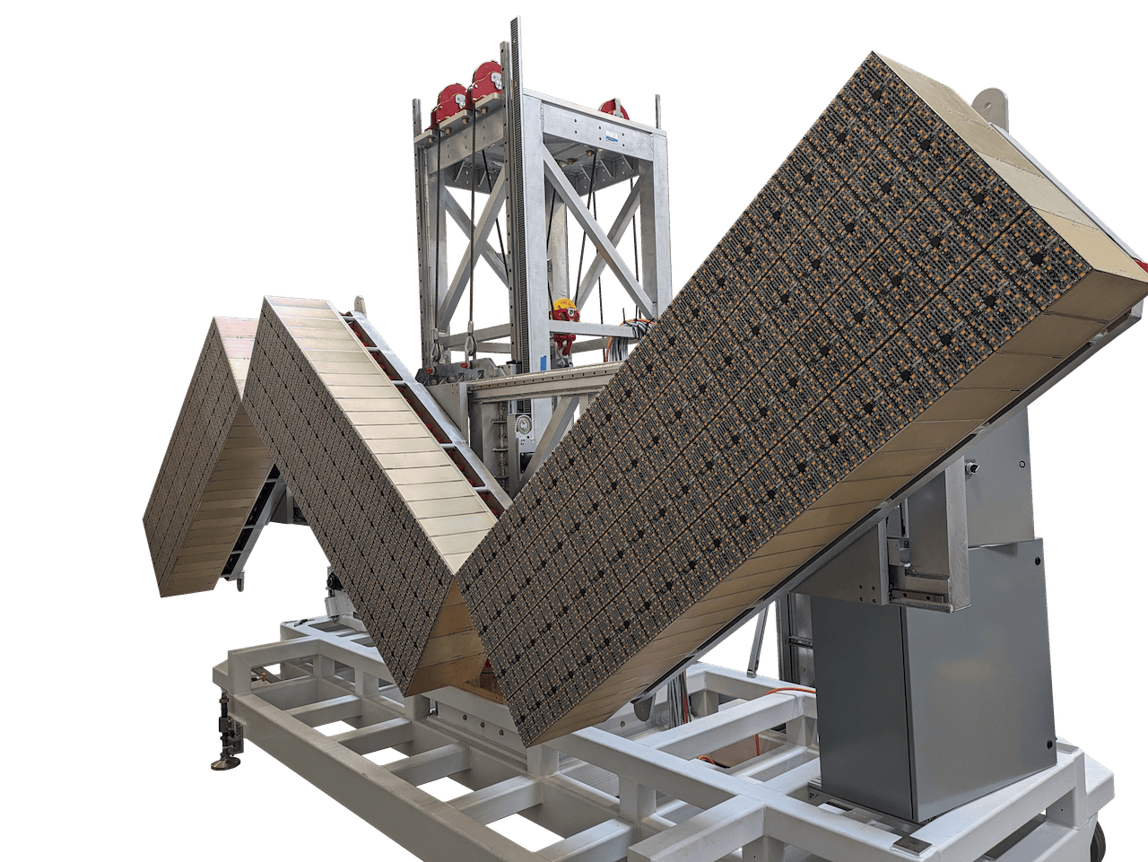
The pantographic morphing array consists of three smaller subarrays that each contain 80 pLEDss heads. Each subarray has its own terminal blocks and cables. Each head’s DC power supply is delivered 220 VAC to allow the use of smaller 18-gauge power wires. Because of the amount of harnessing, it is important to reduce weight and space for the nearly 400 cables running to the breaker boxes.
Based on the early I-format gantry design — which needed to make a U-turn around the support scaffold holding two solar arrays, a floor mounted cable track and a guide system — the total cost for the power delivery alone was estimated to be roughly $200,000. Thanks to the mobile-robot gantry design with simple extension cordage, this expense was reduced to $6,000 and only 150 feet of cable.
While the entire project could have been accomplished with a large, track-based I-format gantry, simplifying the design with mobile robots significantly reduced system complexity and costs.
Contact us to learn more.